Dario Cabib, Alon Segal and Jacob Dolev
ABSTRACT
CI Systems has been involved in the development and production of in-flight boresight equipment since 1989, by pioneering the field with innovative laser-FLIR and laser-CCD alignment solutions.
In addition, over the years we have developed a number of systems for use on the ground to align the various electro-optical instrumentation to a common Line of Sight (LOS) before the mission. This adjustment is very important for the success of the mission: the more accurate the alignment and its retention during the flight, the better the chance of a precise hit. In this paper we describe various systems developed and built at CI for use with EO pods mounted on aircraft, especially UAV’s.
The most important engineering tasks are design for optical alignment retention over a wide range of environmental conditions and convenient mechano-optical interfaces for different pods allowing system compactness and low weight, and easy operation. Some of the design considerations to meet these challenges will be given here.
INTRODUCTION
It is clear that the higher the boresight accuracy between a laser designator and the camera used to image the selected target (a FLIR or a CCD), the higher the probability of successful hit at a longer distance. The same can be said for a laser range finder, providing important information on the designated enemy target.
CI Systems has been involved in the evelopment and production of laser-FLIR and laser-CCD boresight devices since 1989, with the Night Targeting System (NTS) laser designator-FLIR, Direct Vision Optics (DVO) and CCD boresight system deployed on Cobra helicopters. The pioneering development work is documented in references 1 and 2. The NTS boresight system, shown in figure 1, was mounted on the Cobra helicopter for boresight test and correction to 50 μrad. accuracy before firing a missile.

Figure 1: Laser-FLIR and laser-CCD boresight device with small enough dimensions to be mounted on the Cobra helicopter, allowing
boresighting with 50 μrad. accuracy
The basic idea behind the boresight method developed by CI for laser-FLIR alignment was finding a sturdy material (called “Thermal Target”) that when illuminated by a focused NdYag laser heats up and emits thermal infrared radiation in the 3-5 and 8-12 microns ranges of sensitivity of the FLIR.
As explained in reference 1, in order for the system to work without synchronization between the laser pulses and the FLIR frames we had to physically model and work out the right material thickness, absorption depth, emissivity and focusing parameters so that the small heat spot would persist for a long enough time to be sensed by many FLIR frames, but not enough time for the heat spot to spread to a useless size and heat up the whole Thermal Target.
In addition to these requirements, the Thermal Target material had to be strong enough to withstand many laser pulses for as long as possible, yielding significant device reliability. To reach this high reliability a large number of tests were done on a number of different materials before material selection. Since those years CI Systems has used this method in different test instrumentation for infrared weapon devices in the production and development stages.
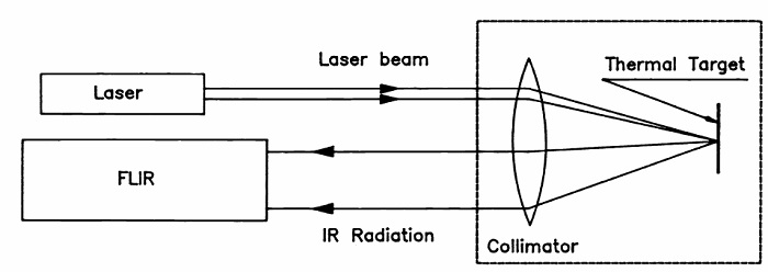
Figure 2: Diagram (figure 1 of reference 1) showing the method of laser/FLIR boresighting using the Thermal Target concept.
Referring to figure 2 the thermal radiation emitted by the Thermal Target due to being heated by the focused laser is transmitted to the FLIR through a collimator in a direction opposite and parallel to the laser beam.
Since the laser beam is focused onto a small spot by the same collimator, the FLIR shows a spot on its screen designating the laser beam direction. By rotation of the FLIR or by software adjustment of the FLIR crosshair the FLIR Line of Sight (LOS) can be precisely aligned with the laser beam.
The alignment can be done with the same method between a laser beam and the LOS of a CCD based camera or day viewing device if the material used on the focal plane of the collimator emits visible radiation as a response to the laser light. This boresighting concept has been used by CI over the years in various testing systems as one of the many tests being performed in development, production or maintenance of many electro-optical weapon systems.
In this paper we describe the way this boresighting concept has been implemented in a specific family of instruments specially built for testing airborne weapon systems in a pod before a mission, without the need to remove the pod from the platform.
TESTING EO PODS ON UAV’S
Figure 3 shows a typical UAV (in this case a Heron model by Israel Aircraft Industries) with its EO pod mounted on the underbelly. Mission readiness depends in large part on the well functioning of the instrumentation mounted on the aircraft.
The price spent on testing this instrumentation just before a mission may in many cases be worthwhile with respect to the price paid for a partly unsuccessful mission due to instrument malfunctioning. One of the important parameters of instrument well functioning is the LOS coincidence of the various sensors and lasers.
These sensors and lasers may be present in the pod of the aircraft in different combinations and configurations of size and performance specifications. We will show here boresight testing of three types: one example that includes only a 1.064 μ laser and a FLIR, and two examples between a laser range finder (LRF) and a FLIR and CCD.
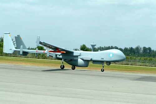
Figure 3: Typical UAV with the EO pod on the underbelly.
Night-Laser Ground Boresight Unit (NGBU)
Figure 4 shows the optical diagram of the boresight system used in this case. The laser beam enters the system through the “Laser entrance window”, it is reflected and focused by the “Parabolic mirror collimator” onto the Thermal Target and the Thermal Target emission is collected by the mirror and collimated back towards the FLIR through the “FLIR exit window”.
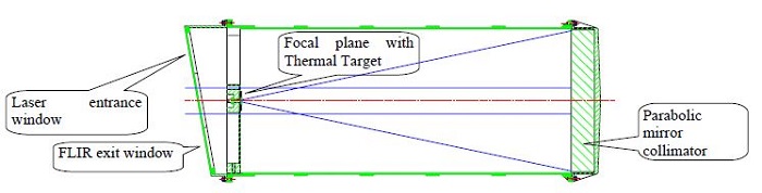
Figure 4: Optical diagram of the NGBU boresight testing system.
Figure 5 shows the NGBU system attached to a shroud for protection from the laser beam and placed on a trolley to be rolled under the UAV pod for testing.
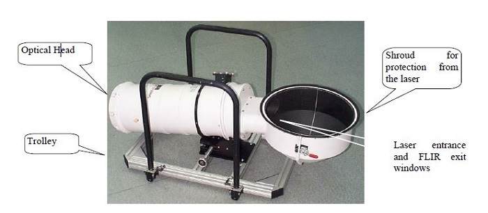
Figure 5: The NGBU system with a shroud attached to it for protection from the laser beam and placed in a trolley to be rolled to the UAV pod.
NGBU characteristics
The NGBU system is relatively large, at least compared with similar systems described in the next sections. Its main characteristics are:
Overall NGBU:
1) Weight: 19 kg
2) Dimensions: 1000 mm x 580 mm x 530 mm
Performance
a. Boresight Accuracy (Line-of-Sight): 50 μrad.
b. Entrance Window (Laser):
1) Transmission: 1.064 μ
2) Diameter: 70 mm
c. Exit Window (IR):
1) Transmission: 3 ÷ 5 μ
2) Diameter: 70 mm
d. Thermal Target:
1) Angular projected thermal target size: ±3 mrad
e. Tracking Target (for rough pod alignment in front of the NGBU windows before boresight test):
1) Size: 0.6 mrad
2) Offset: ±0.2 mrad
f. Temperature Difference between Thermal Target temperature and heated spot: T ≥ 50 C.
Environmental performance
a. Operating Temperature: -25 C - +55 C
b. Storage Temperature: -20 C - +71 C
c. Altitude: 10,000 ft operating, 40,000 ft non-operating
d. Vibration: 2g, 5 to 55Hz
e. Relative Humidity (non condensing): Up to 95%
Boresight systems for pods including FLIR and CCD
When a CCD is included in the instrumentation suite of the pod an additional complication is introduced in the design of the boresight testing device. In fact now the thermal target of figure 2 may not be suitable for the laser-CCD alignment since the CCD may not be sensitive to the reflected laser radiation and the target in general does not emit any radiation
in the wavelength range of sensitivity of the CCD.
A brute force solution is to add in the focal plane of the collimator of figure 2 a suitable target for the CCD but this requires an additional complication in the actual operation of the system: a manual or motorized mechanism for switching between the laser-FLIR and laser-CCD boresighting tests.
This complication is efficiently and elegantly avoided by using a material for the thermal target which can do both: the required heating in the focused laser spot to be sensed by the FLIR and at the same time emit radiation to be sensed by the CCD.
CI has found such a material (let’s call it “material X”) and is now using it for this application. In addition, in such systems, described below, CI has designed the optics so compact that the instrument is significantly smaller than the NGBU above.
Mini-POP system
In this application, developed in cooperation with Tamam, the laser is a single pulse 1550 nm laser, and the boresight requirements are between this laser, the FLIR and the CCD of the system. Figure 6 shows the Mini-POP CBA (or Compact Boresight Assembly).
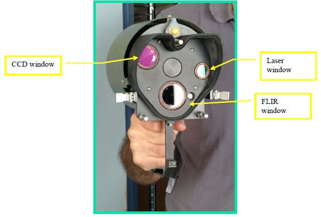
Figure 6: The Mini-POP CBA (Compact Boresight Assembly). It allows boresight test among the pod’s laser, FLIR and CCD.
Figure 7 shows the system when mounted on the pod for testing.
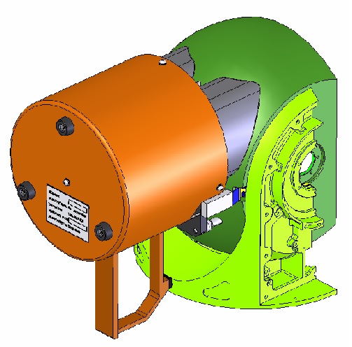
Figure 7: The Mini-POP CBA mounted on the pod for testing.
Mini-Pop CBA characteristics:
Weight and Size:
1) Weight: 1.85 kg
2) Dimensions: 238.5 mm x 192 mm x 145 mm
Performance
a. Boresight Accuracy (Line-of-Sight): 100 μrad.
b. Entrance Window (Laser):
1) Transmission: 1550 nm
2) Diameter: 18 mm
c. Exit Window (IR):
1) Transmission: 3 - 5 μ
2) Diameter: 28 mm
d. Exit Window (VIS):
1) Transmission: 550 nm
2) Diameter: 28 mm
e. Target:
1) Angular projected size: 20 mrad
Figure 8 shows the optical diagram of the system.
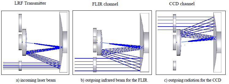
Figure 8: Optical diagram of the Mini-POP CBA. a), b) and c) are different sections of the optics in different planes. In a) the laser beam enters the Mini-POP and is focused on the Target (material “X”); in b) the infrared self-emission due to heating by the laser is collimated through the FLIR window towards the FLIR; in c) the radiation from X is collimated and transmitted to the CCD through the CCD window.
The collimator of figure 8 is composed of a concave parabolic mirror on the right side of a), b) and c) with a flat section in the center to fold the optical train and make the system very light and compact (1.85 Kg. altogether). The target ”X” is on the focal plane in the region of the converging beam. The best boresight alignment that can be reached here is 100 μrad.
The POP300D CBU (Compact Boresight Unit)
This is a similar system to the Mini-POP CBA, but with some differences.
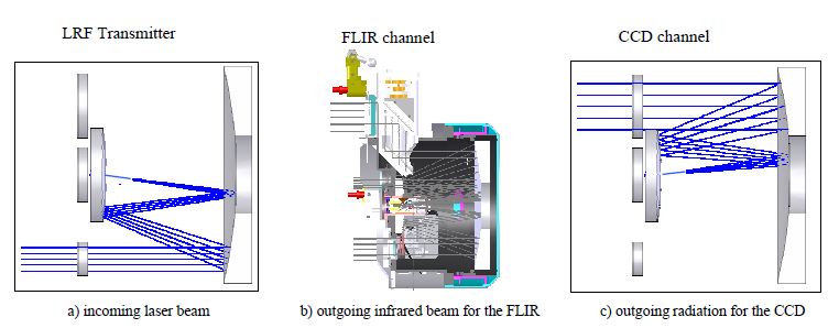
Figure 9: The optical diagram and configuration of the POP300D BSU
The collimating optics with its compactness is preserved but the FLIR channel is translated accurately parallel to itself by a periscope unit in order to fit the UUT (Unit Under Test) optical configuration without increasing the size of the CBU. Figure 10 is a picture of the CBU.
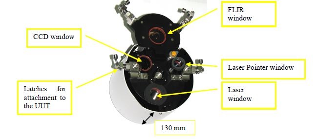
Figure 10: The CBU for POP300D.
As shown in figure 10 the 300 millimeter focal length of the collimator is reduced by the folding of the optical beams shown in figure 8 and 9 to about 130 mm. thickness of the BSU envelope.
POP300D CBU characteristics:
Weight and Size:
1) Weight: 2.4 kg
2) Dimensions: 222 mm x 141 mm x 185 mm
Performance
a. BRST Accuracy (Line-of-Sight): 100 μrad.
b. Entrance Window (Laser):
1) Transmission: 1064 nm
2) Diameter: 20 mm
c. Entrance Window (pointer):
1) Transmission: 830 nm
2) Diameter: 14 mm
d. Exit Window (IR):
1) Transmission: 3 - 5 μ
2) Diameter: 25 mm
Exit Window (VIS):
1) Transmission: 550 nm
2) Diameter: 28 mm
e. Target:
1) Angular projected size: 20 mrad
Video 1 shows an example of successive FLIR images of the thermal spot on the Thermal Target, arising from
successive firings of the laser pulses.
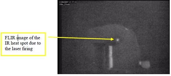
Video 1: IR spot image heated by the laser as seen on the screen of the FLIR. The image is taken on a test set-up and not on the actual boresight testing system. The video clip shows a succession of four single laser pulses occurring approximately about every second.
CONCLUSION
In this paper we have presented a number of implementations of boresight testing systems especially designed for airborne mounted pods with EO instrumentation. The test performed is the LOS alignment of a laser (it can be a designator or range finder) a FLIR and a CCD, in different combinations and opto-mechanical configurations. The accuracy of this alignment is important to aid the fighting units in achieving the highest possible success rate in hitting the selected enemy targets during a mission. The configurations presented here are especially built for UAV mounted pods.
REFERENCES
[1] Cabib, Dario et al., "Boresighting of laser range finder or designator systems with and without laser/FLIR synchronization," Proc. SPIE 1341, 127-136 (1990).
[2] Cabib, Dario et al., "Laser boresighting by second-harmonic generation," Proc. SPIE 1442, 68-80 (1991).