CI Systems offers a cost-effective Integrating Sphere, with highly uniform radiance at the output port and at the VIS-SWIR wavelength range, for testing of imagers that operate in this wide spectral range.
A continuous variable output is achieved using a high-resolution motorized attenuator. Using a variety of light sources the system can be adapted to provide higher Luminance intensities and a wider dynamic range.
Configurations available:
- Standard Integrating Spheres: Offering standard sizes: 1”,2” and 4” output port diameters.
Integrating Sphere, Standard Configuration
- Low-Light Integrating Spheres: Offering lowlight Integrating Sphere for the VIS-SWIR wavelength range at sizes 2”, 4” output port diameters. The system provides highly uniform low light radiance for testing of night vision imagers that require extremely low radiance.

Integrating Sphere, Low Light Configuration
Each configuration is available as a Standalone Unit or an Integrated Unit in Collimator.
Contents:
1. Integrating Sphere Introduction
2. Typical test including integrating sphere
3. Typical mechanical structure
4. Calibration and control
5. Examples of calibration with filtered source
6. Sources and detectors
7. Vis-SWIR Integrating Sphere Sources
Integrating Sphere - Introduction
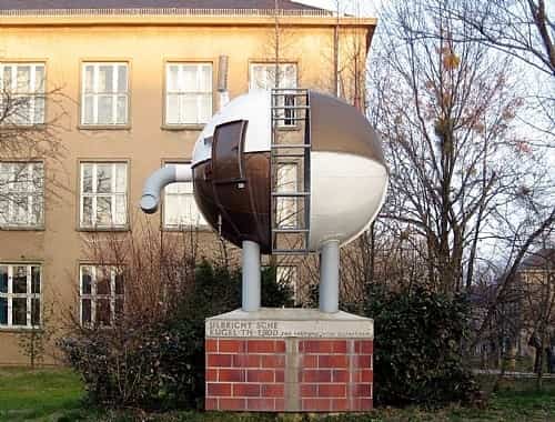
Why is the integrating sphere an important optical instrument? Integrating spheres have been known since the beginning of the 20th century, when Richard Ulbricht published his work in 1900 on their implementation.
Ulbricht sphere statue at the University of Dresden:
Typically, it is difficult to build a visible or near infrared source, to be used as a test and calibration standard for certain sensor characteristics, because for this purpose it has to be a very uniform spatially extended source, radiating uniformly in all directions hemispherically. This is especially true for very high color temperature sources of visible light, because they are made of hot filaments. A very hot filament may produce high intensity of light, but by nature it is a spatially non-uniform source.
High spatial uniformity of light intensity of an extended source is required for example when testing the spatial response of a detector array or when the cross section of an optical projection system exit pupil must be illuminated uniformly.
Light from a glowing lamp, undergoing many internal reflections in an integrating sphere, exits from it as a source of equal intensity from every point of the exit port and into every direction. As a result, such source may be used in different important configurations, for example as a backlight of test patterns for characterization of a camera resolution or other camera characterizing parameters. A polarized light beam entering an integrating sphere exits unpolarized: this feature also may have specific applications when a polarized laser or LED must be used as a source.
Analogously to a conduit for light exiting an illuminating source, an integrating sphere fulfills a corresponding task in collecting the total amount of light being reflected and scattered into different directions from a sample to be measured. This is important for example when i) a sample is highly non-specular and one wants to measure the total reflected light from it, and ii) in measurements of total transmittance of a highly diffusive sample. These types of measurements are very common in research of remote sensing applications.
CI, as a company expert in producing highly sophisticated infrared test and calibration sources and systems, has recently added the integrating sphere to its product portfolio. The integrating sphere is an important complement to the set of building blocks that CI produces, because it enhances the number and types of tests that the customer can do with their test system, increasing its usefulness, and as a result extract higher benefit from their purchase.
Typical CI test system including an integrating sphere subsystem
In figure 2 a typical test system is shown. It includes the projection optics represented by the parabolic mirror on the right side, usually of a large diameter exit pupil to fill the entrance aperture of a unit under test (UUT, typically a visible camera), the secondary mirror, a wheel including a number of test targets, such as a USAF target set, pinholes, knife edges, etc., for different standard tests, the blackbody infrared source (it can be an extended area or a cavity source, used for FLIR’s) and finally an integrating sphere subsystem (IS).
The target wheel is on the focal plane of the projection system; the IS includes the visible light source on its entrance port, a control light detector on a second port at right angle with the entrance port and with the exit port, a third exit port near the target wheel at the focal plane. The IR source and IS system are placed on a motorized stage, so that they can be exchanged automatically by computer control, according to which source must be used and which test must be done.

Figure 2. Schematic optical diagram showing the typical arrangement of the blackbody, target wheel and IS system with respect to the optical projection mirrors. In this case the IS is being used with its exit port on the focal plane. By controlling the stage position, an IR blackbody may be used instead.
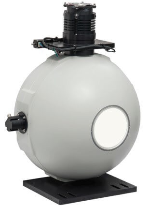
Typical mechanical structure of a CI integrating sphere
In figure 3 three examples of CI standard integrating spheres are shown, with controller. As can be seen, the source on the top, the monitoring detector on the right and the exit port in the front are arranged at 90 degrees to each other; this arrangement, with special baffles built in the interior of the sphere, prevent the detector and the exit port to be illuminated directly by the source, ensuring almost perfect randomization, as required.
These arrangements are most convenient for CI’s sources, with a mechanical fixture on the bottom, when they are used on the focal plane of a collimator as in figure 2, and the light exit is in the horizontal direction. In reflectance and transmittance measurements the light port may be set with light exiting vertically up or down, with different illumination directions on the sample to be measured. In these cases the standard CI IS may have to be modified.
_20191210112712.112.JPG)
Figure 3. Three examples of CI standard integrating spheres and controller. The sphere diameters and apertures are respectively 12”/4”, 8”/2”, 4”/1”. The source and shutter motor are seen on top, the monitoring detector on the right and the light exit aperture in the front. Weights are between 1 and 5.5 kilograms respectively. A mounting fixture is seen on the bottom of each sphere.
Calibration and control of sphere illumination output
CI integrating spheres are spectrally measured and calibrated in the plant before shipment, by measuring the spectral radiance output with a NIST traceable spectroradiometer. In addition, in order to insure stability of calibration with time, despite changes of source output due to aging or line fluctuations, the integrating sphere is equipped with a monitoring detector and feedback loop control on a shutter.
This shutter is placed in front of the light source and is finely controlled in a way that the light exiting the sphere remains constant, at the level selected by the user. For this purpose, the radiance spectrum at the output is measured at calibration for each shutter position and integrated in the wavelength region of interest: this integral value is saved in the system memory as a calibration table versus the monitoring detector reading.
During subsequent years of use of the system, once the user selects the needed radiance value at the output, the system automatically adjusts the shutter to the corresponding position according to the previously built calibration table.
In the following figures we show an example of measurement results, used for calibration in two situations:
- The sphere is used with a broad band source,
- The sphere used with the source spectrally filtered in specific narrower spectral ranges.
In figure 4 we show a typical spectral radiance measurement of the light exiting a CI integrating sphere as function of wavelength, when illuminated with a quartz-halogen lamp, in different shutter positions.
_20191210112830.675.JPG)
Figure 4. Spectral radiance measurement emitted by a CI integrating sphere as function of wavelength, when illuminated with a quartz-halogen lamp, in different shutter positions. On the right side is the list of readings of the monitoring detector, to be used in the calibration table, for automatic shuttering.
In figure 5 we show the radiance values of the spectra of figure 4 integrated in the region of 400 to 720 nm as an example, as function of the detector readings of figure 3. This is in fact the calibration table used in the shutter control in this particular example.
_20191210112917.488.JPG)
Figure 5. Calibration table of output radiance integrated in the 400 to 720 nanometer wavelength range versus monitoring detector signal. The shown R2 value is the standard deviation from a linear fit.
Examples of calibration with filtered source
The CI IS’s are provided with a motor controlled filter wheel that can accommodate eight different filters. These are used when the light output must be limited to a specific wavelength range. A similar radiance calibration in each filter range, together with shutter feedback control for stability, can be done in each spectral range separately. Following is an example of such calibration using three filters (red, green and blue ranges) and respective calibration tables analogous to figures 4 and 5 above.
_20191210113009.378.JPG)
Figure 6. Source, filter wheel and shutter construction on the light entrance port of the integrating sphere.
Figure 7 shows the normalized spectra of three filters and figure 8 the respective calibration tables used for shutter control.
_20191210113048.988.JPG)
Figure 7. Normalized transmittance spectra of the three filters used in the present example.
_20191210113123.597.JPG)
Figure 8. Radiance calibration tables of the integrating sphere using a halogen lamp and the three filters of figure 7. The y axis is in units of radiance and the x axis is units of detector digital level reading.
Sources and detectors
Different type of sources are provided as options: Quartz halogen, LED’s or Xe lamp.
The standard monitoring detector is Si, optional is InGaAs.
Feel free to contact CI for more details on available sources.
Vis-SWIR Integrating Sphere Sources
The SR300N series VIS-SWIR based integrating sphere sources are used in testing and calibrating DayTV and SWIR imagers. They can be setup to operate as a standalone source or can be integrated into an Optical Test Bench based on a either a METS or ILET Collimator for performing electro-optical test qualification of the DayTV and/or SWIR imagers.
Tests using CI Systems' Computerized Test Executive, CTE, can be run include but are not limited to MTF, Dynamic Range, blooming, SNR, Uniformity, distortion as well as resolution testing. The VIS-SWIR integrating sphere source can be used as a calibration tool.
With the blackbody radiation source and VIS-SWIR based Integrating Sphere source combined in the test bench, multi-sensor/imagers can be tested as well as boresight measurements done.
For more information