Introduction
Recent years have seen rapid increases in the use of electro-optical payloads comprising lasers and cameras mounted on manned and unmanned aircraft land vehicles and navy vessels. This worldwide trend encompasses applications in surveillance, identification, targeting and ranging, in addition to other civilian, security, and environmental applications. The driver for the increased popularity of such devices has been in market demand from a broad range of unmanned platforms. This demand was met by the technological advances made in visible and infrared cameras and lasers in terms of miniaturization, size, energy efficiency, and cost.
Most of the applications for such payloads require that the various components are precisely aligned on the same line of sight (LOS). This multiplicity of payload imaging channels (for example the visible and the infrared cameras) is necessary for enhancing and completing the information available to the operator about a given object or scene, and the laser (if present) must "range" or "designate" the same object for the mission to succeed. This is called Line of Sight (LOS) harmonization or co-alignment or boresighting. It must be performed to a very high degree of accuracy, usually in the range of 50 to 100 microradians, which is about 3 to 6 thousandths of a degree.
Over the years CI Systems has worked with many electro-optical payload manufacturers and end-users to develop unique customized systems that are used to co-align cameras and lasers to each other and to external reference planes[i], both in manufacturing and when deployed in the field. This is a family of systems called Compact Testing and Alignment Units, or CTUs.
The CTU concept is based on an opto-mechanical system in which the payload’s laser beam stimulates a number of parallel collimated beams, each one entering the corresponding camera of the payload. These beams are imaged as spots on the cameras' focal planes and designate to each of them the laser direction. The laser and cameras' coalignment is achieved by aligning the laser and the cameras so that the spots all coincide on the same position in the scenery. This procedure does not require any external power.
For payloads that consist of imaging channels only, CTUs can be outfitted with an active projected aiming point requiring external power. Numerous variations of the CTU concept have been implemented in different cases, where each variation fulfills the requirements of the specific application, whether it is R&D, production line, pre-mission field testing, on-site maintenance (O-level), or depot support (D-level). Over the years, CI Systems has gained extensive experience developing custom tailored boresight equipment of this type. CI Systems has successfully delivered CTU's for payloads comprising lasers and cameras supporting most combinations of visible and infrared spectral ranges, while adhering to stringent co-alignment and environmental requirements.
This document presents examples of some of the CTUs manufactured and delivered by CI Systems, including information on their mode of use and the key parameters implemented in practice in each case. Customers who are potential users of a CTU are invited to contact CI Systems to discuss the requirements of their applications.
CTU – Principle of Operation
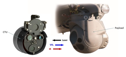
Figure 1: CTU and Payload, a sketch of the co-alignment process
In figure 1 above, the CTU is positioned facing the payload, usually secured in place with special brackets. The laser from the payload is aimed at the CTU’s laser entrance window. The corresponding visible and IR radiation projected on the same axis in the opposite direction of the incoming laser beam, is shown exiting the corresponding CTU ports and entering the payload’s camera ports.
The figures below provide a conceptual depiction of the key elements of a CTU and a cross-section with conceptual ray tracing of a CTU.
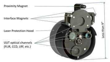
Figure 2: Typical example of the important elements of a CTU
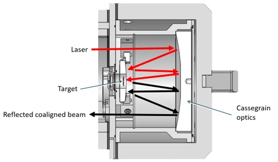
Figure 3: Cross-section of a CTU (typical)
CI Systems CTU Applications
The CTU is useful in the following scenarios:
- In production: the payload manufacturer uses a CTU during the assembly of the payload to ensure the co-alignment of the component LOS's within the required tolerances.
- In the field:
- In airborne system testing: A CTU is used for pre-mission GO/NO-GO testing of the payload channels while the payload is vehicle mounted. This application often introduces unique shock/vibration/environmental challenges to system design.
- For corrective alignment – a CTU is used to correct misalignments discovered in the pre-mission system testing.
- In land vehicle-mounted system testing: such payloads involve special ruggedization requirements typical to all field applications, and specifically for truck-mounted payloads.Such requirements include vibrations, shock, dust, humidity, moisture, and many others.
- In maintenance workshops: Payloads in storage require periodic testing and calibration throughout their lifetime to ensure their continued operability and mission-readiness during periods of storage, which may last years.
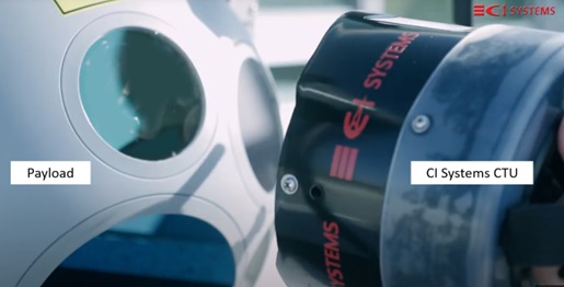
Figure 4: Payload field co-alignment test using a CTU
CI Systems' experience and capabilities in the field of co-alignment
CI Systems has been involved in the development and production of optical co-alignment systems for payloads and camera systems for many years. The Company has developed the ability to respond to its customers’ requirements across the entire spectrum from visible to far infrared, with or without a laser in the configuration.
Following are a few examples of customized boresight tools CI Systems has built for its customers, with their specific characteristics, key features and performance parameters. Contact us to quote solutions fulfilling your needs in the field of optical axes co-alignment.
Example 1:
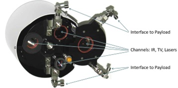
Figure 5: CTU with customized mechanical interface to Payload
Example 2:

Figure 6: CTU with customized mechanical interface to Payload
This CTU type interfaces with the payload through latches for quick and easy mounting.
This CTU features the following channels: IR (MWIR, SWIR), Visible and Lasers (LRF, designator), with parallelism alignment accuracy of 50µRad between all channels' lines-of-sight. The unit is 100% passive, not requiring external power.
This compact CTU weighs 8kg and has been designed for field as well as indoor use, capable of withstanding relative humidity of up to 95%, with an operating temperature range of -25 to +55°C and a storage temperature range of -45 to +70°C.
Example 3:
Figure 7 below shows another example of a CTU for payload alignment. The mechanical payload interface allows easy mounting onto the payload. This CTU features the following channels: 1064nm laser designator, 1550nm LRF, 870nm laser pointer, MWIR camera, SWIR camera and Visible camera. The optical system has a focal length of 320mm and parallelism alignment accuracy of 80µRad between all channels' lines-of-sight.
This compact CTU weighs 3 kg and has been designed for field use as well as indoor use, capable of withstanding relative humidity of up to 95%, with an operating temperature range of -30 to +45°C and a storage temperature range of -45 to +70°C.
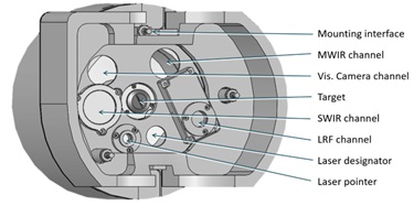
Figure 7: Example of a CTU
Example 4:
Figures 8 and 9 shows a Payload Electro-Optical Alignment and Test System for indoor use. The payload is easily mounted on a quick-mount base plate. The system includes a laser, visible and IR channels. The optical collimator is the standard CI Systems ILET-5-15 collimator .
The electro-optical test system includes additional features such as a carrying box, energy meter, laptop, and power supplies. Unlike the heavily customized CTUs above, this system can support multiple payloads of similar sizes.

Figure 8: Payload electro-optical alignment and test system for indoor use
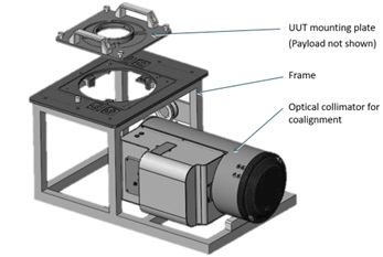
Figure 9: Payload mounting interface
Example 5:
Figure 10 shows a CTU for payload alignment. Here both the CTU and the payload are mounted on a truck. In this configuration, the payload is mounted at a height of 4m above the floor and the CI Systems CTU is mounted next to the UUT on a dedicated plate. The CTU includes a high-resolution collimator with a clear aperture of 220mm.
The CTU includes the following channels: Lasers (1064nm designator, LRF 1550nm, Pointer 870nm), IR (MWIR, SWIR) and Visual Camera. The optical system includes a 320mm focal length collimator with a co-alignment accuracy of 80µRad between all channels' lines-of-sight.
This compact CTU weighs 3 kg and has been designed for field use as well as indoor use, capable of withstanding relative humidity of up to 95%, with an operating temperature range of -30 to +45°C and a storage temperature range of -45 to +70°C.
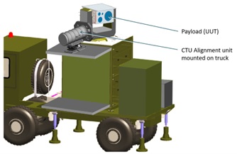
Figure 10: CTU for truck-mounted payloads
Example 6:

Figure 11: CTU for Payloads, including a ruggedized case
Figure 11 shows a CTU unit for payload alignment, including a ruggedized case to withstand a field environment.
[1] Cabib, Dario et al., “Electro-optical systems to accurately align (boresight) laser designator, FLIR and CCD on the ground before the mission”, Proc. SPIE Vol. 7113 71130S-1 (2008).