Introduction: The Unique Challenges of WFOV Testing
Testing modern infrared (IR) imagers with a wide field of view (WFOV), ranging from 10° up to 80° or more, presents unique challenges compared to testing traditional narrow field of view (NFOV) systems.
While standard performance metrics like Modulation Transfer Function (MTF), Noise Equivalent Temperature Difference (NETD), and Minimum Resolvable Temperature Difference (MRTD) are measured using conceptually similar methods for both system types, WFOV imagers demand additional, critical characterization. These imagers are designed for situational awareness, making the spatial and angular accuracy across the entire scene paramount. Consequently, parameters like field of view verification and, most importantly, optical distortion mapping, become essential tests.
NFOV imagers, which typically have fields of view of only a few degrees, are analogous to telescopes. They use long focal length optics to detect small targets at great distances. The test equipment for these systems reflects this, commonly using large-aperture reflective optics (e.g., parabolic mirrors) with long focal lengths. Such systems produce highly collimated IR beams with minimal divergence and are nearly diffraction-limited on-axis, making them ideal for testing high-magnification optics.
In contrast, a WFOV imager is designed to capture a vast area in a single frame. For these applications, the ability to correctly determine the shape and relative angular position of objects across the entire image is often more critical than resolving the smallest details. Even minor optical distortions can introduce significant errors in the perceived angular separation between objects, compromising the system's mission. Therefore, the user of a WFOV imager must have a reliable method to map and correct these distortions.
This requirement places two fundamental demands on the test equipment:
- The WFOV tester must project a collimated scene that is either larger than the imager's own FOV, enabling the characterization of performance out to the very edges of the field, or, for very wide FOV systems, sufficiently large to subtend a sufficiently large portion of the UUT’s Field of View to collect statistically significant amounts of data.
- The tester's own optical system must be rigorously calibrated. Its projection map, the true angular position of every point it projects, must be known with high precision. This allows it to serve as a metrology standard against which the imager's distortion can be accurately measured and subsequently corrected.
CI Systems' WFOV family of collimators is specifically designed to meet these demanding requirements. For flood level testing, WFOV collimators are commonly paired with standalone concave emitter blackbodies.
Understanding Optical Distortion
Imagine a perfect grid of points, as shown in Figure 1. An ideal, distortion-free optical system would project an image of this grid onto its sensor while perfectly preserving the straightness of the lines and the true angular separation between every point.
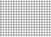
Figure 1: A set of points at the corners of a grid of squares. The central point defines the Line of Sight (LOS)
Optical distortion refers to any deviation from this ideal mapping, causing straight lines in the object space to appear curved in the image. This changes the apparent shape and position of objects. The most common forms of distortion are pincushion and barrel type (shown in figure 2), but even more irregular distortions (not shown) may result from imperfect camera manufacturing:
Figure 2. Left: Pincushion distortion, where points are magnified more as their distance from the center increases. Right: Barrel distortion, where magnification decreases with distance from the center
Even with state-of-the-art design and manufacturing methods, two primary factors may still contribute to distortion in complex lens assemblies:
- Design and manufacturing tolerances of the optical elements: minute variations in lens curvature, thickness, and material refractive index from the nominal design.
- Assembly Tolerances: microscopic misalignments in the positioning, spacing, and tilt of individual lens elements within the optical housing during assembly.
Applications of WFOV Testers
CI's WFOV test systems are essential for a range of critical measurements:
- Core Performance Metrics (MTF, NETD, MRTD): The WFOV family supports all standard electro-optical tests by projecting calibrated targets from an IR source (blackbody) through its refractive optics.
- Field of View (FOV) Verification: The WFOV tester projects a calibrated pattern (e.g., crosshairs or corner markers) that extends beyond the Unit Under Test's (UUT) specified FOV. This allows for precise measurement of the UUT’s actual horizontal and vertical angular coverage.
- Distortion Mapping: Using a precision grid target on the tester's focal plane, the system projects a pattern of points at precisely known angular positions. By analyzing the locations of these points in the UUT's image, a complete distortion map can be generated. This map is the key to creating software-based corrections that restore geometric accuracy to the imager.
- NUC and other flood level testing is accomplished with flat and/or concave emitter blackbody sources to keep the calibration source size manageable. (is the blackbody in this case placed directly in front of the UUT, or is it placed on the focal plane of an optical system?)
The Importance of WFOV Tester Calibration
To accurately measure distortion in a UUT, the test system itself must be a trusted metrology standard. This requires its own projection map to be rigorously calibrated, a process performed by CI Systems during manufacturing.
The calibration is achieved by placing a target with a grid of pinholes at the tester's focal plane, illuminated by an IR source. The tester is placed before a reference camera mounted on a high-precision, two-axis gimbal. For each pinhole, the gimbal is rotated and moved to align the projected IR spot precisely with the camera's Line of Sight (LOS). The gimbal's angular encoders record the true vertical and horizontal angle for that pinhole with respect to the LOS. This process is repeated for the entire grid, creating a calibration map that links every point on the focal plane to a precisely measured angle in space. This map becomes the spatial reference for all subsequent UUT testing.
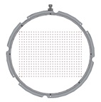
Figure 3: Example of a precision grid target placed at the WFOV tester's focal plane, used for both tester calibration and UUT distortion mapping
The CI Systems Advantage: Standard and Custom WFOV Solutions
Figure 4: Examples of WFOV collimators:A. IR model with a blackbody source, B. SWIR model with integrating sphere source, C. Distortion-mapping collimator for LWIR
Conclusion: Your Partner in WFOV Testing
CI Systems has built deep expertise in the specialized field of wide-field infrared imagers' testing. Our WFOV collimators are built on the basis of proven, modular components, including our industry-leading blackbody sources, target wheels, and automated control systems. These standard products are driven by the same extensive and powerful software platform developed for our traditional METS family of mirror-based collimators.
This modular approach allows us to provide cost-effective, timely, and reliable solutions, whether from our standard product line or as part of a custom-engineered system. We invite you to consult with our engineering team to design the optimal testing solution for your WFOV application.